 English
 فارسی
فارسی русский
 العربية
 Melayu
 हिन्दी
 Indonesia
how can we help you
You can contact us any way that is convenient for you. We are available 24/7 via email or telephone.
Contact us
Working principle of AC contactor: when the electromagnetic coil receives the command signal to get electricity, the iron core is magnetized into an electromagnet, which generates electromagnetic attraction. When the rebound force of the spring is overcome, the moving iron core is attracted to drive the contact to move (the contact system is linked with the moving iron core), that is, the normally closed contact is separated and the normally open contact is closed; When the coil loses power, the electromagnet loses magnetism, the electromagnetic attraction disappears, and the contact is reset under the action of the spring. The working voltage of AC contactor coil should be 85%-105% of its rated voltage, so as to ensure reliable contact. If the voltage is too high, the magnetic circuit of AC contactor tends to be saturated, and the coil current will increase significantly, which is in danger of burning the coil. On the other hand, the voltage is too low, the electromagnetic attraction is insufficient, the moving iron core cannot be attracted, the coil current reaches more than ten times the rated current, and the coil may overheat and burn out.
Contactor structure description: It is composed of several parts such as electromagnetic system, contact system, arc extinguishing device, reset spring, etc. Electromagnetic system: including movable iron core (armature), static iron core, electromagnetic coil; Contact system: including main contacts with large current capacity for connecting and disconnecting the main circuit and auxiliary contacts with small current capacity for controlling the circuit; Arc extinguishing device: used to quickly cut off the arc generated when the main contact is disconnected to avoid burning or welding the main contact. For AC contactors with larger capacity, arc extinguishing grids are often used to extinguish the arc.
After clarifying the principle and structure diagram of the AC contactor, the following introduces how to wire the AC contact line. It is divided into main circuit and control circuit wiring. The schematic wiring is explained first, and then the physical wiring is introduced.
1. Wiring of the main circuit of the AC contactor

The wiring of the main circuit is relatively simple, that is, three inputs and three outputs, top input and bottom output. All six of these must be connected to the main contacts. As the name suggests, the main contacts are used to contact electrical appliances or connected to the main circuit. Pay attention to the exposed copper core. It should not be too long, otherwise it is easy to cause safety accidents. It should not be too short, otherwise it is easy to have poor contact. The screws should be screwed in with a matching screwdriver, and the force should be balanced and moderate. After tightening the screws, pull them hard. If they cannot be pulled off, they are qualified.
2. Wiring of the control circuit of the AC contactor
The control circuit generally uses the auxiliary contacts on the contactor, combined with auxiliary buttons, relays or indicator lights, to realize the power supply . The specific circuit and specific control need to be different. The following is an example of the asynchronous motor starting
control circuit. Case 1, direct starting circuit of the motor
The so-called primary circuit is the circuit elements and wires through which the working current of the motor winding passes: the secondary circuit is an indispensable auxiliary circuit to ensure the normal operation of the equipment. The main functions of the secondary circuit include control, measurement, signal and protection . The circuit that starts and stops the motor is the control function circuit of the secondary circuit; the measurement and display of electrical parameters such as voltage, current, power and power factor are its measurement functions; the operation and stop indicator lights, abnormal alarm sounds, etc. are circuit elements of the secondary signal circuit: thermal relays , motor protectors and other components can realize the motor protection function. The following is a detailed analysis of the working process of the motor direct starting circuit.
In Figure 1, the live wires (phase wires) L1, L2 and L3 of the three-phase power supply are connected to the upper end of the isolation knife switch QS . The function of QS is to disconnect the power supply during maintenance. There is an obvious disconnection point between the circuit under maintenance and the power supply to ensure the safety of the maintenance personnel. FU is the protective fuse of the primary circuit. When preparing to start the motor, first close the knife switch QS. After that, if the main contacts of the AC contactor KM are closed, the motor is powered on: the main contacts of the contactor are disconnected, and the motor stops running. Whether the contactor contacts are closed or not is controlled by the secondary circuit.
In Figure 2, FU1 and FU2 are secondary fuses. SB1 is the stop button. SB2 is the start button. FH is the protection output contact of the thermal relay. Press SB2. The coil of the AC contactor KM1 is energized, its main contacts are closed, and the motor starts to run. At the same time, the auxiliary contact KM1-1 of the contactor is also closed. It enables the contactor coil to obtain continuous working power, and the contactor's pull-in state is maintained. It is customary to call the auxiliary contact KM1-1 a self-holding contact.
During the operation of the motor, if there is an abnormal situation such as overcurrent or short circuit for some reason, the bimetallic strip inside the thermal relay FH (see Figure 1) will be thermally deformed due to excessive current, and within a certain time limit, its protective contact FH (see Figure 2) will be disconnected, causing the contactor coil to lose power, the contactor main contact to disconnect, and the motor to stop running, protecting the motor from being burned by overcurrent. After the protection is activated, the auxiliary contact KMl-1 of the contactor is disconnected, and the motor remains in the stopped state.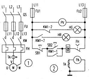
If SBl is pressed during the operation of the motor, the motor will also stop running, and its action process is the same as that of the thermal protection.
The stop indication green light HG and the operation indication red light HR are controlled by the normally closed (break) or normally open (make) auxiliary contacts KMl-2 and KMl-3 of the contactor respectively, and are used as signal indications. The secondary coil of the current transformer TA is connected in series with the ammeter PA, and the voltmeter PV is directly connected to the power line, and they measure the running current and voltage of the motor.
In Figure 2, there is no "·" where the wires are connected in a "丁" shape. There is generally no "·" in electrical drawings. In fact, whether or not to draw a dot here complies with the requirements of the national standard GB4728 " Graphic Symbols for Electrical Drawings". It's just that different application fields have their own drawing habits.
Case 2: Motor self-locking circuit
The first picture is a basic description of the contactor. After understanding the basic structure of the contactor, let's use the second physical wiring diagram to explain the working principle of the contactor. Figure 2 is a basic contactor self-locking circuit. As can be seen from Figure 2, the 3-phase power supply passes through the switch through the fuse to the contactor input. Output to the load . L2 branch passes through the fuse to A1, L3 passes through the fuse branch to the control button SB1 {normally closed: straight through, press to disconnect} SB2 {normally open: disconnected, need to press to connect} and then to A2. Then it is very clear: when we press SB2, the yellow line of SB2 outputs electricity to energize the contactor coil, and the contactor is attracted. At the same time, SB2 is connected to SB1 and extended to the line of the normally open group of the contactor {called: self-locking line} is energized {when SB1 is not pressed}, so when the contactor is activated, the electricity of the self-locking line reaches A2. When we release SB2, the contactor is still in working state, completing self-locking. So when we want to stop, we press SB1, the self-locking line loses power, the contactor is disconnected, A2 has no power, and the contactor coil will not work.

Xiamen Rongfeng Electrical Equipment Co., Ltd. is located in Xiamen, Fujian Province. Its business scope covers East China, South China, North China, Southwest China and other parts of the world. Main DCS control system spare parts, PLC system spare parts and robot system spare parts, advantage brand: Allen Bradley, Bently Nevada, abb, Emerson ovation, Honeywell DCS, Siemens. Rockwell ICS Triplex、FOXBORO、Schneider PLC、GE Fanuc, Motorola, hima, prosoft and other imported industrial parts, the company always adheres to the business philosophy of "integrity, efficiency, win-win and innovation", and serves every new and old customer with the working attitude of "quality assurance, honest service, customer first", relying on competitive product prices, huge inventory and excellent quality, Fast delivery time and full range of pre-sale consultation, after-sales service, continue to provide customers with high-quality products, the main products are widely used in electronics, metallurgy, chemical industry, power plant, steel plant, rubber, cement, mechanical equipment, construction and other industries.
Main products, superior supply and sufficient stock:
All brands DCS, PLC spare parts:
1:Invensys Foxboro: I/A Series system, FBM (field input/output module) sequence control, trapezoidal logic control, accident recall processing, DAC, input/output signal processing, data communication and processing.
2:Invensys Triconex: Redundant fault-tolerant control system, the most modern fault-tolerant controller based on triple modular redundancy (TMR) structure.
Westinghouse (Westinghouse): OVATION system, WDPF system, MAX1000 system spare parts.
3:Rockwell Allen-Bradley: Reliance Ryan, SLC 500/1747/1746, MicroLogix/1761/1763/1762/1766/1764, CompactLogix/1769/1768, Logix 5000/1756/1789/1794/1760/1788, PLC-5/1771/1785, etc.
4:Schneider Modicon: Quantum 140 series processors, control cards, power modules, etc.
5:ABB: Industrial Robot Spare Parts DSQC Series (No. 2, No. 3, No. 4, No. S4C, No. S4C, IRC5), Bailey INFI 90, etc.:
6:Siemens (SIEMENS):Siemens MOORE, Siemens Simatic C1, Siemens CNC system and so on.:
7:Motorola (Motorola): MVME 162, MVME 167, MVME1772, MVME177 and other series.
XYCOM:I/O, VME board and processor.
8:GE FANUC (GE FANUC): modules, cards, drives and other spare parts.
9:Yaskawa (ochuan): servo controller, servo motor, servo driver.:
10:Bosch Rexroth (BOSCH Rexroth): Indramat, I/O module, PLC controller, drive module and so on.
11:Woodward (Woodward): SPC valve position controller, PEAK150 digital controller.
Spare parts for industrial robot system
Advantage Brands: ABB Robots, FANUC Robots, YASKAWA Robots, KUKA Robots, Mitsubishi Robots, OTC Robots, Panasonic Robots, MOTOMAN Robots, etc.If you need, we can solve your defect part or exchange. Welcome to inquire! We will give you the best service!


 IPv6 network supported